Saturday, 22 December 2012

Multi-output Expression Pedal

I've got three Moogerfoogers on one of my pedalboards (Ring Mod., Low Pass Filter and FreqBox), and use a Moog EP-2 expression pedal to control the mix on the Ring Mod. If I want foot control of anything else, I either need more feet or the discontinued (and expensive) Moog MP-201. I wanted to explore a more practical compromise - adding more outputs to the one EP-2.

The aim is to have four outputs, all controlled at the same time by the one expression pedal, but each with its own maximum level, so that some can produce more subtle changes than others. The outputs also need an on/off switch and an LED to show that they're active.

The inputs on the 'foogers correspond to the front panel knobs. Increasing the voltage level at the input adds to the knob setting, rather than overrides it. The voltage can be generated externally or derived from the 5.6V provided on the 'ring' connection of the stereo connector. The EP-2 normally takes this 5.6V supply, divides it through a pot controlled by the pedal, and feeds it back to the input.

The multi-output version needs to take the pedal pot output and distribute it to the four individual output pots, whose wipers are connected through switches to the output sockets. That's the concept, but it won't work in practice because the pots will interfere with each other if they are just wired in parallel. Also, the 5.6V supplied by the 'fooger can't drive much current, and it's quite likely to be overloaded.

The 5.6V needs to be buffered with an op-amp and the pedal pot's wiper further buffered four ways so that each output's pot is isolated from the others. The current comes from a new external 9V DC input. Adding the switching, LEDs, and ground lifts (in case loops cause noise), this is the circuit I ended up with:


IC2 is powered from the 9V DC input and buffers the 5.6V taken from the first output connector. This output feeds the expression pedal pot and powers four rail-to-rail op-amp buffers IC1 & IC3, whose inputs are taken from the pedal pot wiper. Each of these outputs is fed to an individual output pot and on to the switch.
The physical design is constrained by the space available inside the EP-2 box:


Although there's quite a lot of space, I won't be able to get the whole circuit on one board mounted to the side, where I want the controls. So it's going to be two boards, one for the pots, switches and LEDs, another for the ICs and connections to the output sockets and expression pot. This is a start:


The output socket pattern should allow right-angled plugs to be fed in from the rear.

Control panel drilling done, although no LEDs yet:


After squeezing the LEDs in:


The pots have small, serrated shafts instead of knobs - they won't need to be set very often. The strip at the bottom is the connector to the other board. The lack of space forced a few compromises when it came to soldering. It's not pretty:


Installed in the EP-2:


The other board is less constrained, space-wise, and has two connectors and the op-amps etc.:


The connector at the bottom is for the sockets, 9V and expression pot. Almost finished:


The boards connected together:


Assembled, tested, and in-situ:
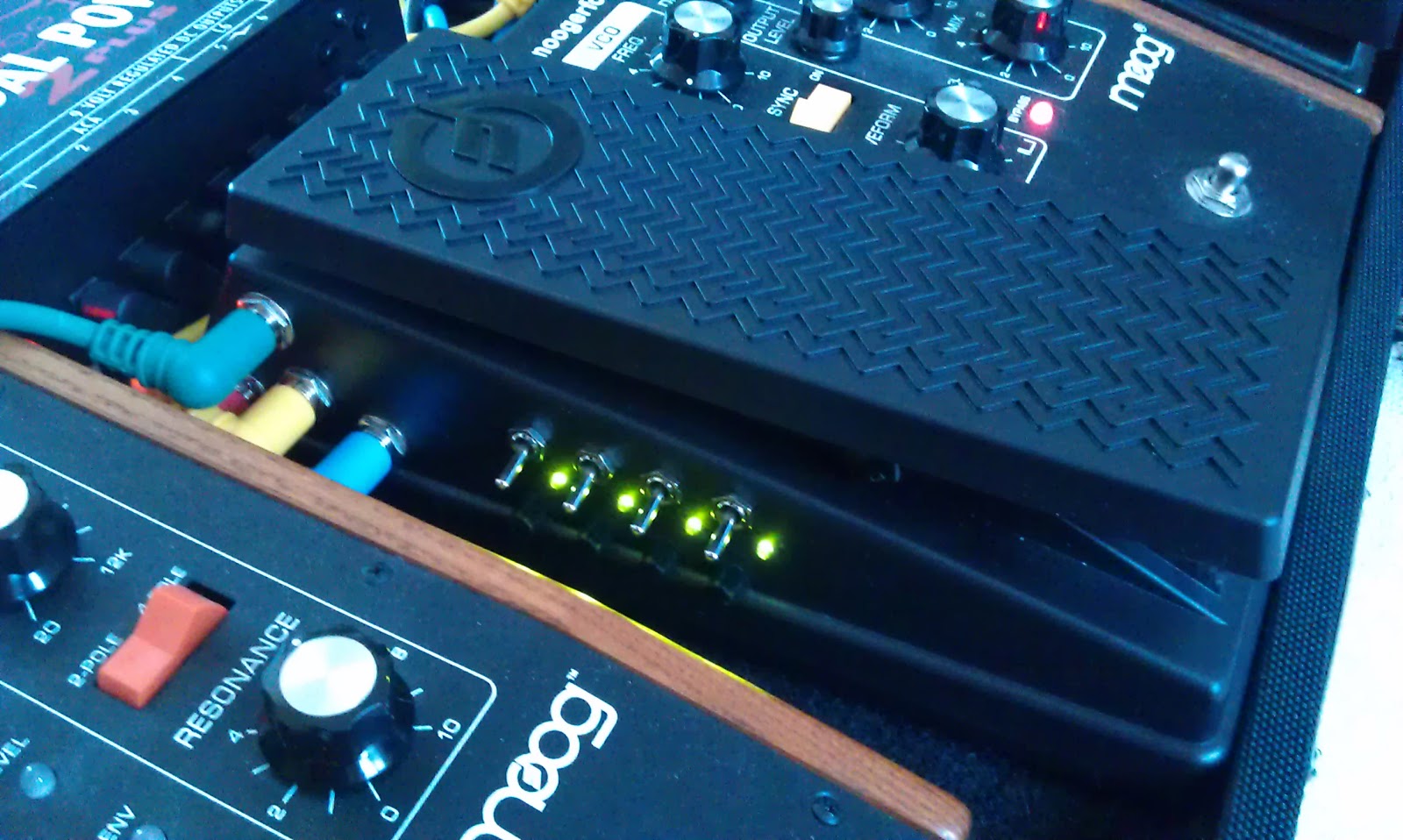

The whole board:


Initially I'm using the modified EP-2 to control the Ring Mod's mix, LPF's resonance and the FreqBox's mix and frequency.

It's been a challenging but very enjoyable and satisfying project. I made a few mistakes, learned a few lessons, and got some ideas for future projects. For example, it would be nice to be able to invert the output signal so that as one parameter is increased, another is decreased.

Sunday, 28 October 2012

Moogerfooger switch box

For a while I've had my 'fooger MF-101 Low Pass Filter's envelope output connected to the frequency input of the MF-102 Ring Modulator. It makes some very nice noises, but I'd like to have the option to disconnect the link mid-song, to get normal ring mod. There's a small space on my board between these two pedals so I decided to see if I could make a simple box with a footswitch, using bits I already had.

This is the circuit:


I added a pot to allow the level of the envelope signal to be reduced, but not turned off altogether. There's also an LED so that I can see whether the connection is closed or open.

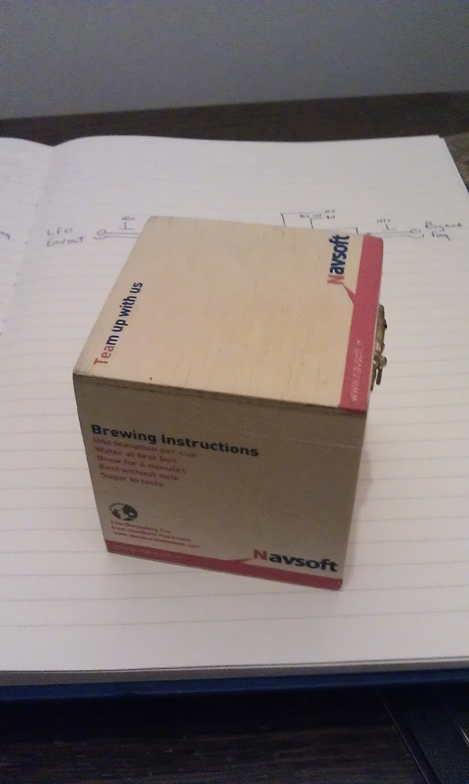
For some reason, I've got a small wooden box that previously had tea in. It fits the available space and is also a bit taller than the 'foogers themselves - ideal for a footswitch that is going to live behind other pedals. It'll also be easy to make holes in:


Some drilling and soldering later, this is what I ended up with:


On the board:


Finished, with some velcro underneath:


In context:

I ought to post some recordings. Don't hold your breath...

Thursday, 11 October 2012

Teasers

Here are some grainy pictures of the things we're working on at the moment. Write-ups and hi-res pix to follow.


Saturday, 2 April 2011

MIDI Trigger


This box translates footswitch inputs to MIDI note on/off messages. We're using this to trigger a sampler with some special Zaardy noises on. It has three banks of three notes. The notes are played using the three footswitches on the left. The bank is selected using either the red button on top of the box or the single footswitch on the right.

It's based on an Arduino Uno, a microcontroller with handy digital inputs for the footswitches and serial out for MIDI.

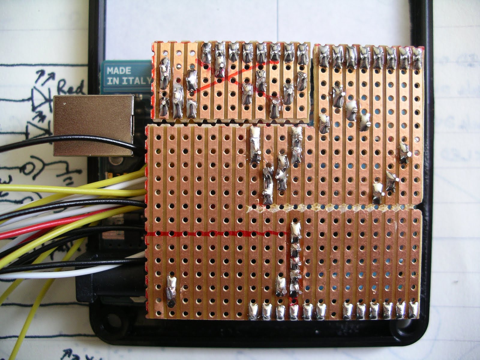
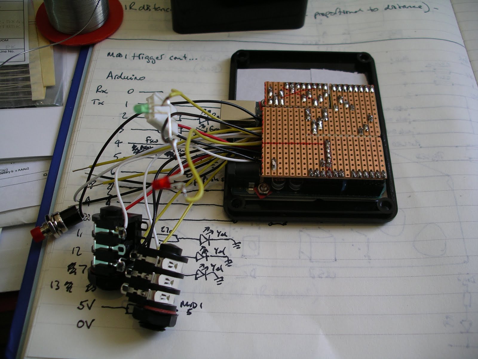
The electronics is straightforward - mostly LEDs, resistors, connectors and wires:


The Veroboard sits on top of the Arduino but has to be in two parts because the pin spacing is non-standard.


Plastic boxes are not very robust for live use, but they're much easier to make holes in than metal:


Assembled:


The LEDs are power (red), triggered (green), bank (yellow).

Software

To make the Arduino read the footswitch states and send the appropriate MIDI messages requires some bespoke software. The Arduino comes with a framework to help with this, so that all you have to do to read a digital input (footswitch) is:

state = digitalRead(pin);

...and state will be either HIGH or LOW.

Playing MIDI notes is also easy:

Serial.print(0x90 | (channel-1), BYTE);
Serial.print(note, BYTE);
Serial.print(velocity, BYTE);

To put this together into a complete application takes quite a lot more code, and this is what I ended up with:


The .h & .cpp files on the left are C++ classes, each performing some discrete function. They all get put together in the code on the right. The final application is downloaded to the Arduino through USB.


Future developments - Three notes are OK, but what we really need is thirteen:


This is the next project...

Friday, 1 April 2011

The Electric Violeg

Category: Rustic Homebrew

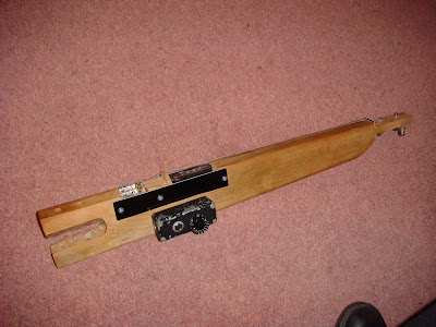
What does it do? - this is a two-stringed electric fiddle made from the amputated leg of an old table and some old guitar parts. And some Meccano. It's made entirely of things I had lying around the house and garden, the only thing I had to buy was the bow, which was the cheapest factory second I could lay my hands on. It sounds vaguely violin-ish, but in what I think is quite a good way. It's seen a good bit of usage on stage and in the studio.

 
This is the first attempt. The neck was much too fat to play at this stage. 

Strings anchored by strips of Meccano.

3-ply plastic strips are shielded with foil and connected to ground via the Meccano to reduce hum from the single-coil pickup. With no body to enclose the output jack and volume control, an old die-cast box was fitted to the side.

Front view of the one-a-side headstock.

Addition of crudely-carved chin-rest and corderouy-upholstered shoulder pad. 

Rear view of head, tuners mounted upside-down to conserve space.

The slimmed-down neck makes the top notes accessible to people with normal fingers.

Originally this was to be played under the chin, but it was found to be easier to have it mounted vertically on a microphone stand like a tiny 'cello. Parts of a mic clip are now permanently attached to the rear for ease of mount and dismount. It was also found to be useful to mark the notes faintly on the fingerboard with pencil, and wear a head-mounted torch when playing the instrument under stage lighting. Mark can be seen demonstrating this in the picture at the top of the article.

Future Developments? - I quite like the idea of having a quartet of these, one for each leg of the table.


Thursday, 31 March 2011

Casio MT-40 Sequential Voice Switch

Category - Modification


What is it? - a circuit added to a Casio MT-40 keyboard to rapidly switch between four voices. It could also be adapted to switch audio or control voltage sources.

How does it work? - I've lost the circuit diagram (I made this back in 2005), but it's pretty basic. The MT-40, in common with many Casiotone keyboards of the early '80s has two keyboard modes; "Play", where the keys function in the standard musical fashion, and; "Set", where the keys are used to select the voice, or Tone as Casio call it. Each white key selects a Tone, the names of which can be seen just above the keys.
The slider switch which toggles between these modes is just out of shot to the right. To the right of that is another switch labelled "Tone Memory", which allows you to change between four pre-selected tones without changing to the "Set" mode. I found that rapidly moving this switch whilst playing made a cool sound, but I could only play one-handed. So I decided to automate the rapid switching.


The circuit I built to do this is a standard sequential switch that I found many variations of online. The larger IC is a 4017 decade counter, triggered by a 555 timer, the speed of which is determined by the value of the capacitor and the potentiometer. Four of the 4017 outputs are connected to the Base pin of each of the transistors (by way of indicator LEDs, and buffered by 1M resistors, as the unit runs at 7.5v). The Collector and Emitter of each transistor are connected to the four pairs of contacts in the "Tone Memory" switch. The 5th output of the 4017 is connected to its reset pin so it counts to 4 rather than 10.

The picture below shows the circuit installed into the MT-40 enclosure. To the far right are the controls - an on/off switch and a rate knob. To the left you may be able to make out the empty slot where the Tone Memory switch used to be.


Further Developments? - I set to building a variation on this which was to have +/- 5v power and transmission gates in the place of the transistors, which would allow me to cycle rapidly through up to 10 audio signal paths (or more if a second 4017 was added). My intention was to build something like a step-wah, but it turned out that somebody was already making one, so it quite literally never got off the drawing board.

Another use that this might be put to is sequentially linking bend-points in a circuit-bent device to create a rhythmic pattern. An external trigger input could be substituted for the 555 so that this could be synched to a multitrack by sending the device an audio pulse e.g. an isolated click.

Credits: Big thanks are due to Imogen on this one!