Some of my Axoloti patches these days require more than the three footswitches I've got with my original pedalboard controller design. I allowed for future expansion of the controller and the signals required for additional footswitches are available on a free RJ45 (Ethernet) connector. There's no room on the pedalboard but I can have a standalone switch box plugged into the controller and put it just in front of the existing footswitches. It means a bit of extra setup at gigs and rehearsals but that's acceptable.
The spare connector has 0V, 3.3V and six I/O pins. I can use three of those directly for the footswitches - they just need to connect the input to 0V when pressed (the Arduino pins have internal pullups). The remaining three pins can be used to drive LEDs, although not directly. To keep the Arduino code the same for the new LEDs and to avoid overloading the outputs we need some transistors to turn the LEDs on, with the current coming from the 3.3V supply. So an external PCB is needed and this also is a good way to isolate the controller from any mechanical stress of having a standalone footswitch box connected and disconnected regularly.
The PCB schematic:
It's not ideal that the only available power rail is the Arduino's 3.3V. The risk is that the footswitches and/or the associated LEDs induce glitches or noise on it, risking causing the Arduino to misbehave. The main footswitch uses the raw 9V for that reason. So, apart from the transistors and their base and collector resistors, I added some decoupling capacitors and a series 10 Ohm resistor to try to protect the 3.3V supply. The resistor values were chosen after experimentation. 2k2 is quite high for LEDs but I don't like them to be too bright so they'll be fine.The layout:
What it should look like:
There will be a short Ethernet cable from the controller to the PCB and the new footswitch box will be plugged into the other RJ45.
Nine days after ordering them from JLCPCB for the incredible price of less than £4 including shipping, the PCBs arrived:
I fitted the surface mount components first. Easier with a microscope:
Before I could test it I updated the Arduino firmware to support the additional footswitches and LEDs, and also added them to the iPad layout in MIDI Designer.
I had a footswitch test board kept from the original controller development. As the connections for the new box are the same as on the original, I was able to use it to prove that all the switches and LEDs worked as expected before building the new box.
The PCB needs to be mounted in the small free area on the pedalboard. I decided to raise it up a bit so designed and 3D printed some supports:
The end result:
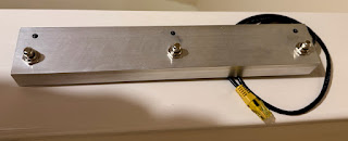
The new footswitch box is just some aluminium channel. I couldn't find a standard enclosure with the right dimensions. I drilled some holes:
Then added the switches and LEDs and a suitable length of Ethernet cable:
Initially it won't have sides or a bottom. I may add them in future for extra protection. As it is the wiring is securely tie-wrapped to some chunky copper wire I used for the 0V connections. It shouldn't move in use or in transit.
Testing was easy - I just repeated what I'd done earlier with the test board. Happily the wiring was good and everything worked.
It's intended to sit just in front of the pedalboard, offset from the other footswitches to make it less likely that I'll hit the wrong one. I'll have to see whether this is the best arrangement long-term.


Hello
ReplyDeleteDeeply impressed by your blog content which means a lot to electronic enthusiasts.
This is Liam from PCBWay. I’d like to sponsor your project by providing free PCB prototyping,
only hoping for a slight promotion or a review about quality or service in return.
Would you be interested in partnering up? Contact me: liam@pcbway.com