
A few years ago I built an Arduino-based gadget with two CV outputs, a footswitch and an output for controlling an EHX Freeze pedal:

I wrote patches with oscillating or random CVs and used them to drive my Moogerfooger MF-101 Low Pass Filter. Now that I've got three 'foogers and a CV-controllable KOMA BD101 delay, it's time for an upgrade.
MK2 has a lot more features:
- Eight 5V CV outputs for Moogerfoogers
- Six 9V CV outputs for the KOMA delay
- CV input from the KOMA sensor
- Six opto-isolated outputs for the Freeze, tap-tempo and (maybe) looper control
- MIDI support - for patch development and live control
- Expression pedal input
- CV input for Moogerfooger LPF envelope
- Three footswitches with LEDs
- Based on the much faster Arduino Due

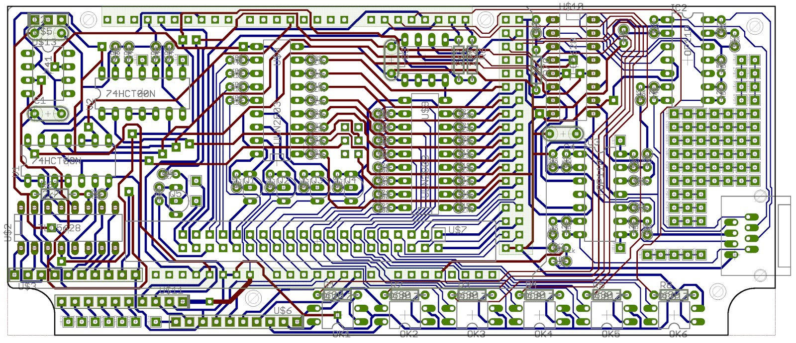
The Arduino is mounted vertically at the back of the box, with a shield PCB sitting on top of it. A ribbon cable connects the shield to another PCB that lies just below the upper surface, with a 4-digit, 7-segment display, up/down patch select switches and four RJ45 sockets at the front. Two more Veroboard PCBs with TRS connectors mount on the front panel and connect to the shield through PCB header/crimp connectors. The shield schematic looks like this:


I built the easy one first:


Then the shield:


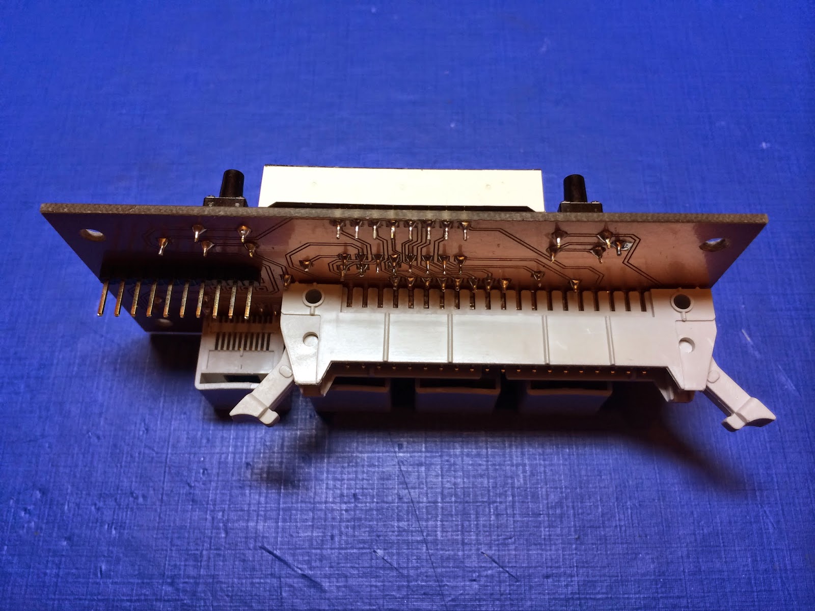
Fitting the display PCB into the box:


I built the TRS Veroboards and fitted them into the box:


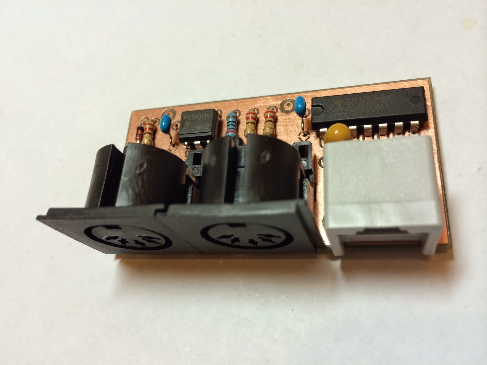
One of the RJ45s brings out a 3.3V serial port from the Arduino. So I needed an external board to translate to MIDI:

The next phase of the project is to write the Arduino firmware and find or write an application to configure the patches from a laptop or iPad. It'll be a while before the original box is replaced on the pedalboard...
No comments:
Post a Comment