The aim is to have four outputs, all controlled at the same time by the one expression pedal, but each with its own maximum level, so that some can produce more subtle changes than others. The outputs also need an on/off switch and an LED to show that they're active.
The inputs on the 'foogers correspond to the front panel knobs. Increasing the voltage level at the input adds to the knob setting, rather than overrides it. The voltage can be generated externally or derived from the 5.6V provided on the 'ring' connection of the stereo connector. The EP-2 normally takes this 5.6V supply, divides it through a pot controlled by the pedal, and feeds it back to the input.
The multi-output version needs to take the pedal pot output and distribute it to the four individual output pots, whose wipers are connected through switches to the output sockets. That's the concept, but it won't work in practice because the pots will interfere with each other if they are just wired in parallel. Also, the 5.6V supplied by the 'fooger can't drive much current, and it's quite likely to be overloaded.
The 5.6V needs to be buffered with an op-amp and the pedal pot's wiper further buffered four ways so that each output's pot is isolated from the others. The current comes from a new external 9V DC input. Adding the switching, LEDs, and ground lifts (in case loops cause noise), this is the circuit I ended up with:

IC2 is powered from the 9V DC input and buffers the 5.6V taken from the first output connector. This output feeds the expression pedal pot and powers four rail-to-rail op-amp buffers IC1 & IC3, whose inputs are taken from the pedal pot wiper. Each of these outputs is fed to an individual output pot and on to the switch.
The physical design is constrained by the space available inside the EP-2 box:

Although there's quite a lot of space, I won't be able to get the whole circuit on one board mounted to the side, where I want the controls. So it's going to be two boards, one for the pots, switches and LEDs, another for the ICs and connections to the output sockets and expression pot. This is a start:

The output socket pattern should allow right-angled plugs to be fed in from the rear.
Control panel drilling done, although no LEDs yet:

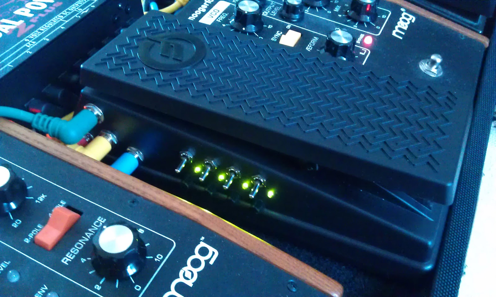
After squeezing the LEDs in:

The pots have small, serrated shafts instead of knobs - they won't need to be set very often. The strip at the bottom is the connector to the other board. The lack of space forced a few compromises when it came to soldering. It's not pretty:

Installed in the EP-2:

The other board is less constrained, space-wise, and has two connectors and the op-amps etc.:

The connector at the bottom is for the sockets, 9V and expression pot. Almost finished:

The boards connected together:

Assembled, tested, and in-situ:
The whole board:

Initially I'm using the modified EP-2 to control the Ring Mod's mix, LPF's resonance and the FreqBox's mix and frequency.
It's been a challenging but very enjoyable and satisfying project. I made a few mistakes, learned a few lessons, and got some ideas for future projects. For example, it would be nice to be able to invert the output signal so that as one parameter is increased, another is decreased.